
Project
This study demonstrates the application of Cadence CFD Software on a generic missile, the ANF (Army-Navy Basic Finner). It is a typical test geometry, meaning that there is plenty of reference data available to the public, making it ideal for comparison and validation of various numeric methods. The reference data is taken from US Army Research Laboratory Report ARL-TR-6725 (November 2013), showing both free-flight test and wind tunnel data, in a huge speed regime from Ma 0.5 to Ma 4.25.
Geometry and Domain Preparation
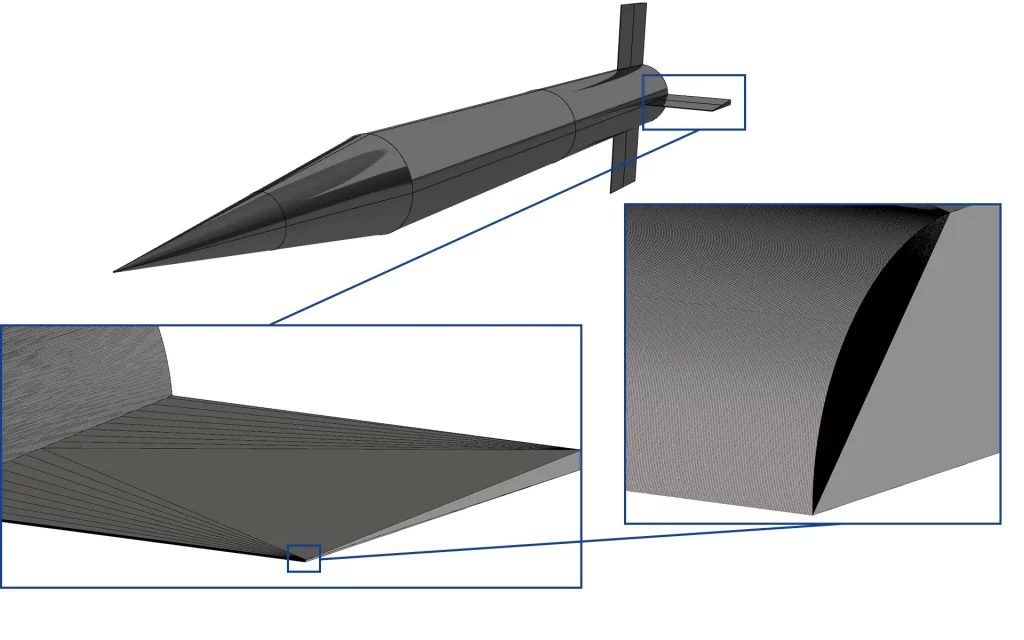
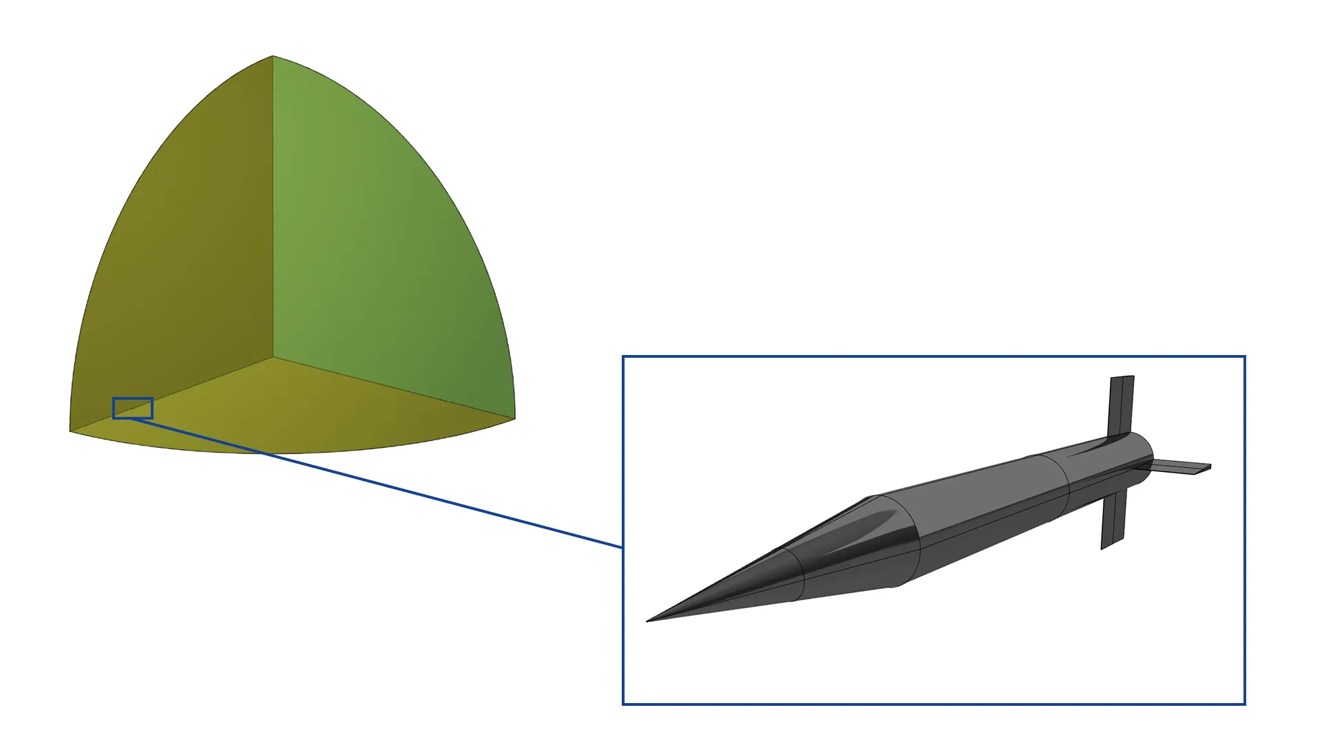
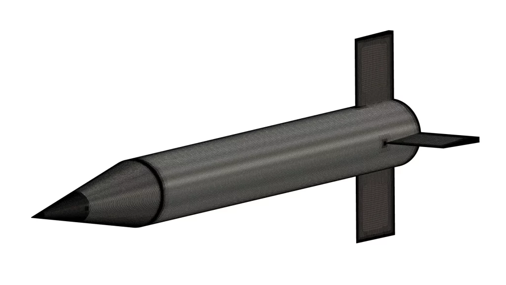
The geometry of the ANF is quite simple and can be taken from Figure 1. The dimensions are given in calibre (1 calibre = 0.03m), meaning that the missile is 0.3m long, the various free fight models weighted 1.5894 kg. Since a low Reynolds approach was targeted, small near-to-wall cell sizes are required for such high speeds. This in turn also requires a fine triangulation of the geometry, also when keeping the very small radii at the missile nose and fin leading edges in mind (0.12mm). An indication of the triangulation can be taken from Figure 2. For most of the simulations a large 1/8th sphere was used (R=20.0m, see Figure 3), making use of two symmetry planes for the cases at 0° angle of attack. Some configurations required an AoA of 1° however, making it necessary to increase the domain to 1/4th sphere.

Mesh Generation
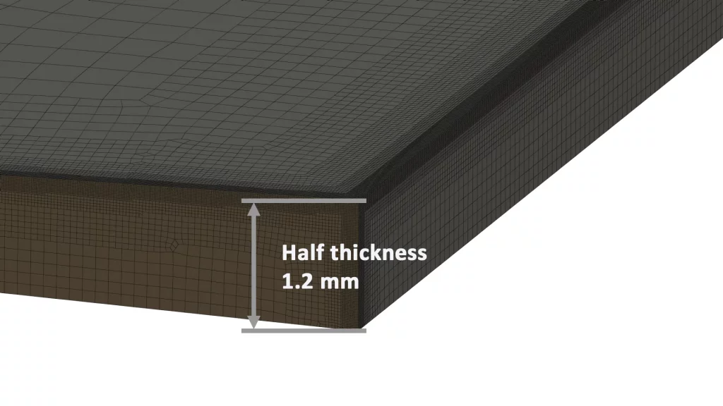
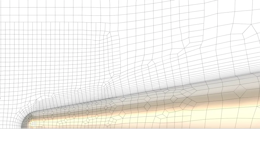
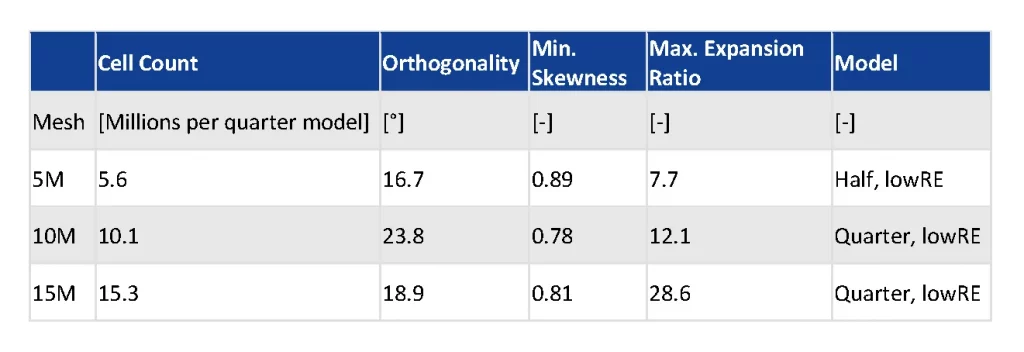
Pure hexahedral numerical grids were generated to achieve a high mesh quality while keeping the cell count reasonable. Three grids of different density were created, an overview on cell count and quality is given in Table 1. Special attention was given to flow relevant features:
- Missile cone and the tiny nose
- Fin leading edges
- Blunt fin trailing edges
- Blunt missile aft body
- A thin wall type refinement in the core wake
- Target (y+ < 5)
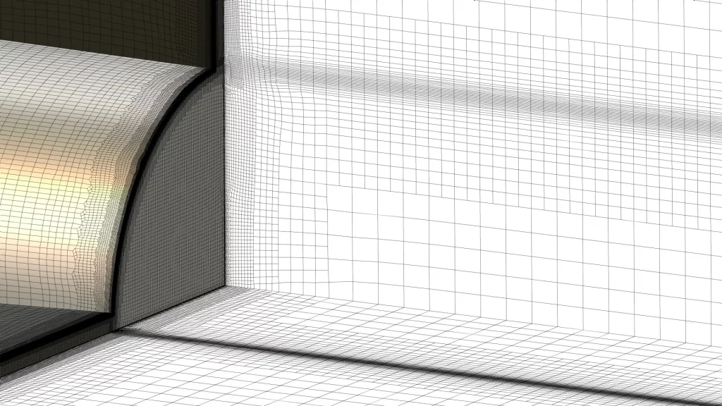
Some impressions of the fine (15M cells) mesh are given in Figure 4 to Figure 7.
Case Setup and Pre-processing
In all simulations the CPU-Booster was used, both during coarse grid initialisation and on the fine grids (CFL up to 500). Some other specifics were:
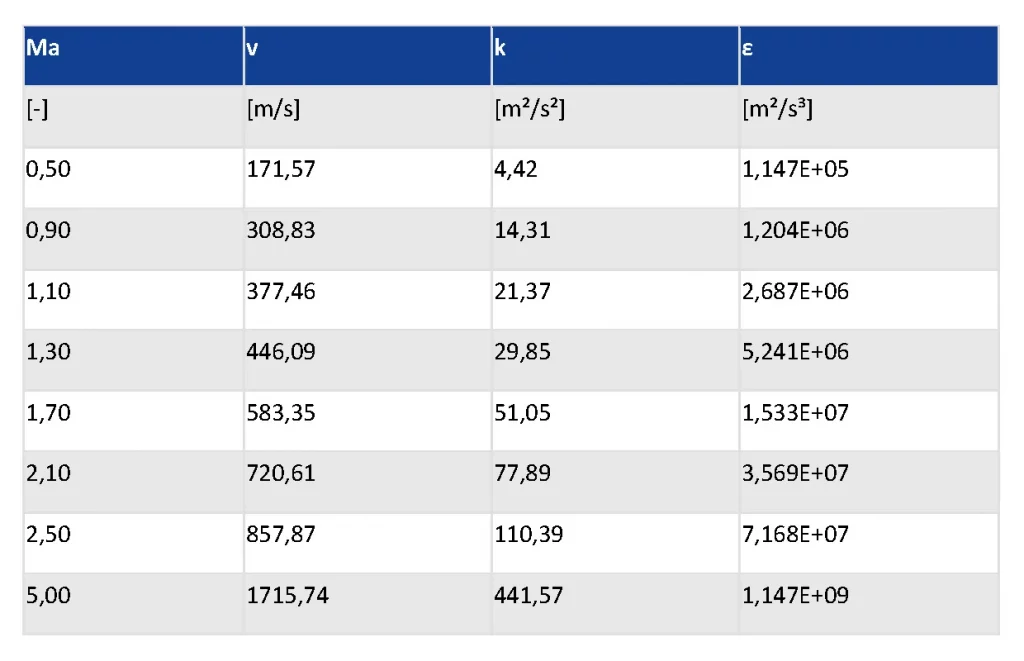
- Inlet turbulent quantities depending on free stream velocity (for 1% intensity and viscosity ratio of 1; Table 2)
- Air prefect gas model (a comparison with real gas showed a drag difference of less than 1% for Ma 2.5)
- SSC-EARSM turbulence model (separation sensitive corrected, anisotropic)
- Comparison of two numerical schemes:
- Classic Jameson-type dissipation scheme (Matrix-scheme)
- Low-diffusive flux splitting scheme (LDFSS)
Quantitative Results
The reference data contains results ranging from Ma 0.5 to Ma 4.25 and were taken from wind tunnel experiments, as well as free flight tests (using numerous single-usage projectiles!).
Three coefficients are of main interest:
- Drag coefficient Cx0
- Lift coefficient derivative CNα0, CN,alpha0
- Moment coefficient derivative Cmα0
While the drag coefficient can be derived from only one simulation at 0° angle of attack, the lift and moment coefficient derivatives are calculated from two simulations at AoA 0° and 1°, respectively.
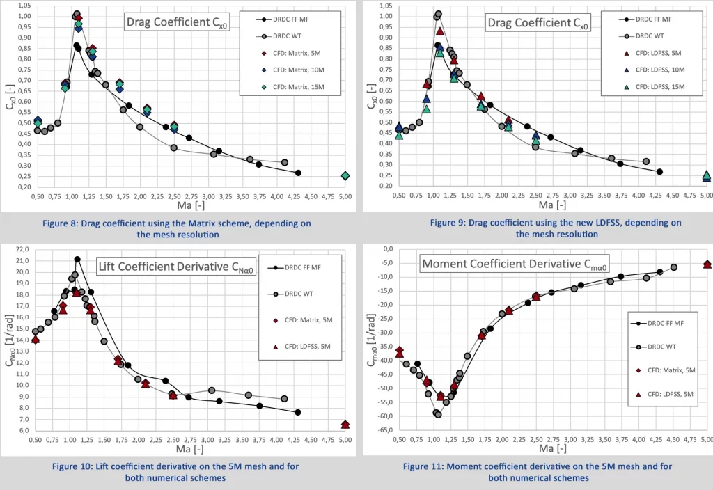
When comparing the experimental results for the drag only, significant differences can be observed: around Ma 1 wind tunnel tests (WT) indicate a quite higher drag coefficient than the free flight tests (FF), while above Ma 1.5 this is reversed. From Ma 3 on the experiments seem to converge towards comparable values (Figure 8, Figure 9).
Both CFD schemes and the grid resolutions show a clear trend:
- Matrix scheme: drag coefficients vary slightly with grid resolution, for Ma >> 1 an overshoot of the 5M and an undershoot of the 10M mesh is indicated when comparing to the 15M cells mesh. Overall trend of CFD data is very good, however in general drag is a bit higher than in both experimental tests.
- LDFSS (low-diffusive flux-splitting scheme): a clear trend in grid resolution is observed, drag values converge with increased cell count over the full operating range. Overall trend is again very good, but the new, less diffusive scheme shows substantial decreased drags for all Mach numbers, being very close to the wind tunnel data below Ma 1.5. Above that speed CFD results are close to the wind tunnel test until finally converging to 0.25 drag coefficient at Ma 5.
The lift and moment coefficient derivative are shown in Figure 10 and Figure 11. Again, the CFD results match very well, also the sharpness of the extremum in both curves is captured nicely. For these data only the small 5M cells mesh is applied (actually this is 5M per 1/8th of a sphere as also given in Table 1, making the full domain 10M cells), so no grid study was performed here. But the two numerical schemes were applied, and for these coefficients the differences are far smaller.
Now, who would do CFD and check numerical values only? Exactly, every CFD engineer likes qualitative results in colourful pictures! The space in this case study is limited, but a few impressions can be taken from Figure 12 to Figure 14:
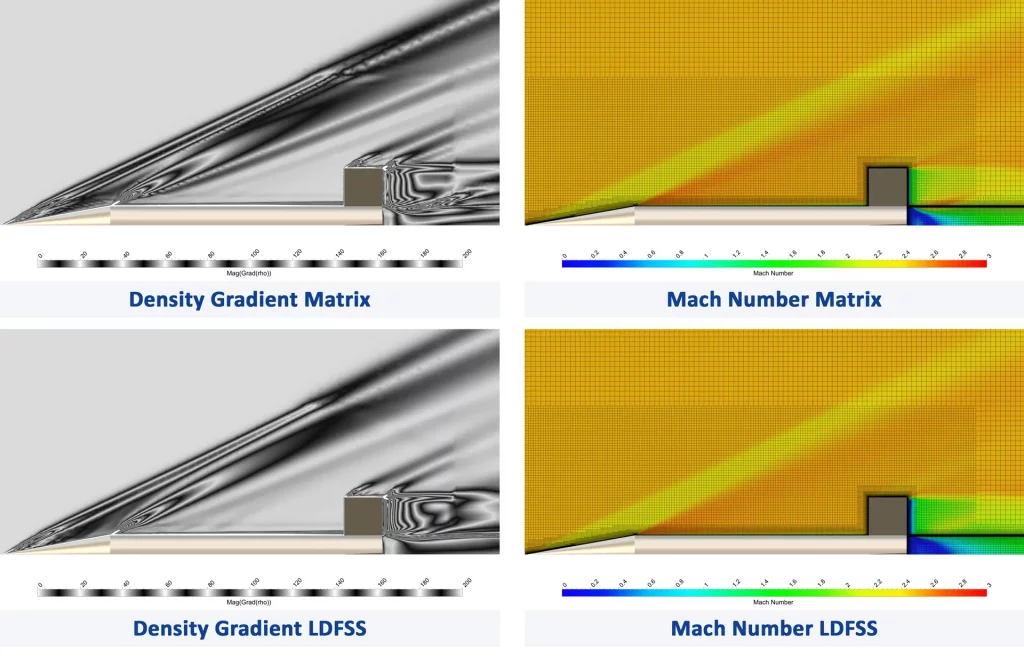
- Figure 12 shows the missile at Ma 2.5 on the fine (15M) grid, comparing the numerical schemes for the density gradient and the Mach number. Some of the flow features seem to be sharper with the LDFSS scheme (gradient), also the angle of the shocks is slightly impacted. The mesh cut on the right side shows a refinement zone around the missile, and the changes in cell sizes can be easily correlated to some changes in the flow features.
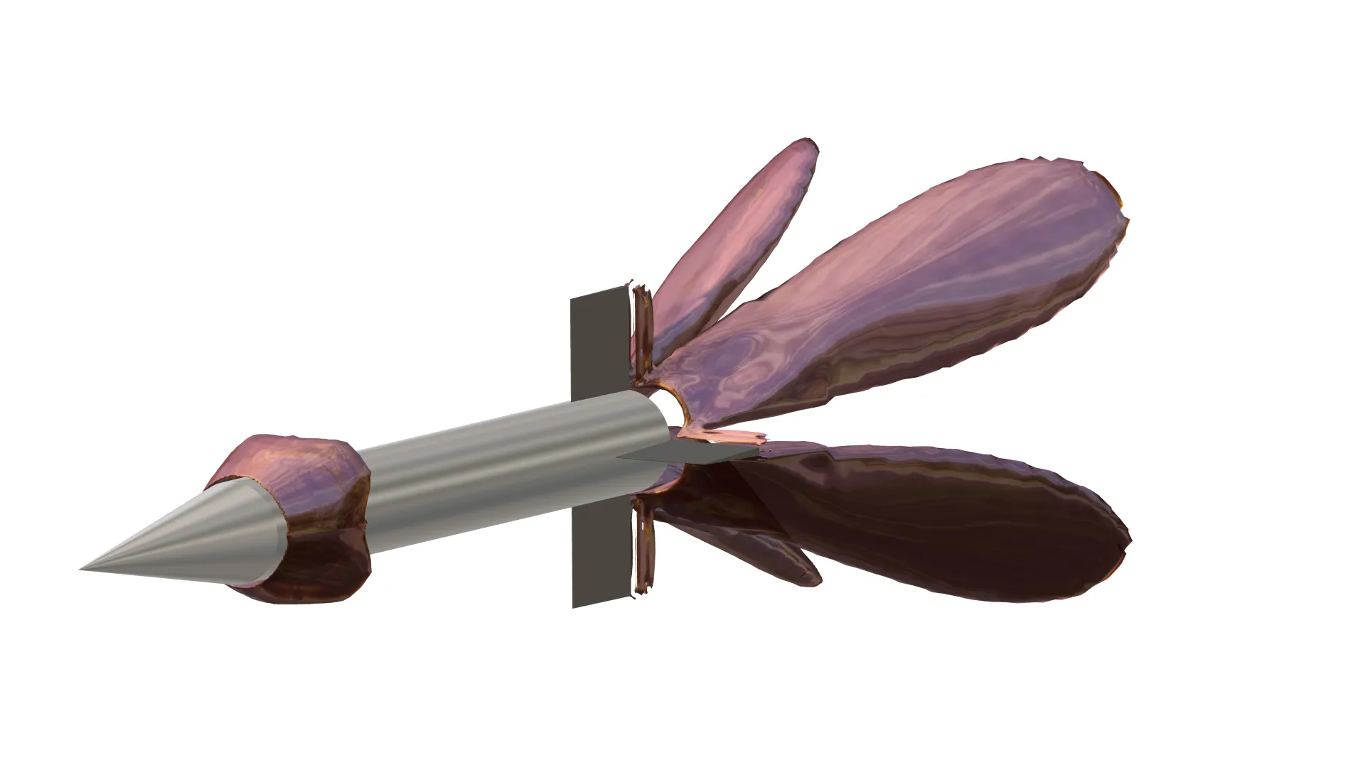
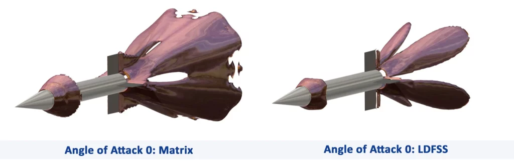
- Figure 13 shows again Ma 2.5 and the fine mesh, now displaying an iso-surface of Ma 2.6. The patterns are very different for the two schemes, especially in the fins’ wake and the interaction with the main body wake.
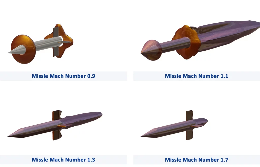
- In Figure 14 the development of a Ma 1 iso-surface with the missile velocity is given, starting from Ma 0.9 until Ma 1.7.
Overall, the results are very good, matching all the trends in the experimental data. A great leap in accuracy can be achieved by just switching to the new LDFSS, which reduces the numerical diffusion and hence improves especially the missile drag, and is applicable at all flow speeds.
Feel free to give it a try!