
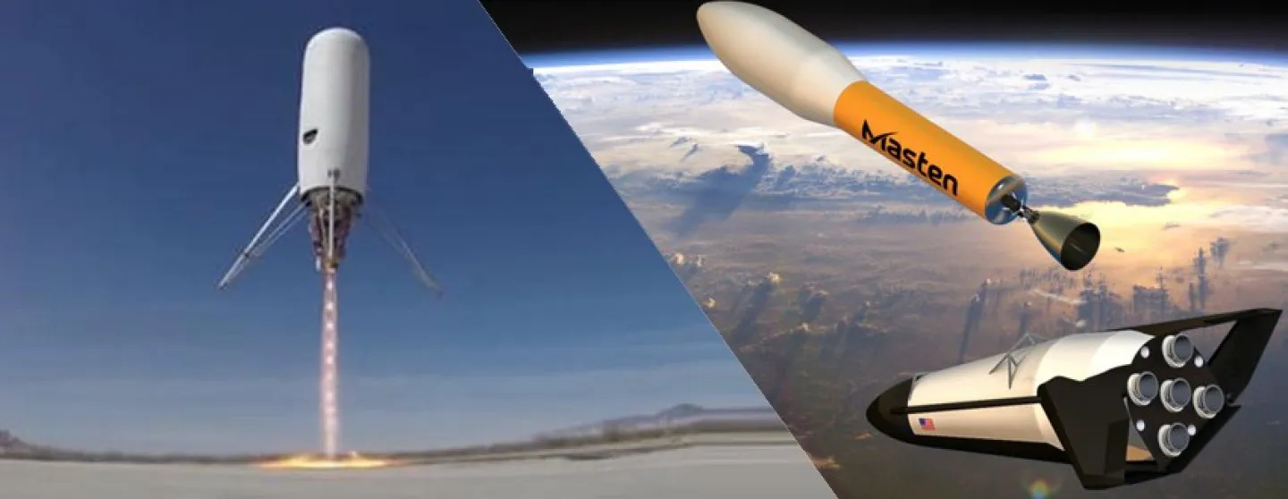
Masten Space Systems is a private company founded in 2004 and headquartered in Mojave, California, USA, by David Masten. Masten’s focus on reusable rocket technology is driven by the goal of enabling space transportation and reliable planetary landers for the Earth, Moon, Mars, and beyond.
One of Masten’s recent pioneering space flight vehicle projects was to design a reusable aircraft designed to fly to the edge of space, the XS-1. The XS-1 aircraft will be capable of launching a 3,000-pound spacecraft to the earth’s orbit at a cost of $5M, which is ten times less than today’s launch systems. A key objective of the program is to fly the XS-1 10 times in 10 days in order to demonstrate its “aircraft-like” operability, cost efficiency and reliability. Key anticipated characteristics of the aircraft include a physical size and dry weight typical of today’s business jets.
One of the new innovations in this effort is a full-scale additively manufactured aluminum thrust chamber assembly for the 25,000 lbf LOX/LCH4 dual expander propulsion system. The dual expander cycle offers an ideal cycle in this size range, enabling reusability, optimal closed-loop performance, and cost effective design and production price points.
CFD for the simulation, analysis and optimisation of critical spacecraft components
Masten Space Systems is using Fidelity Flow Solver with OpenLabs, Cadence’s unstructured multi-purpose CFD solver package, for the design and analysis of various elements of reusable spacecraft and lunar vehicles for the testing of thrust chambers. In this article we talk about the numerical studies of three of their aeronautical configurations.
Simulation of plume impingement and thermal load
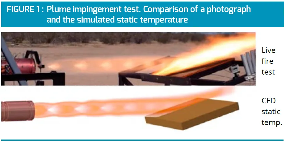
For the testing of thrust chambers, Masten Space Systems had to determine the temperature on the impingement plate in order to avoid reaching critically high temperatures. To do this, they simulated the impact of a hot plume at multiple times the speed of sound and a temperature hotter than the melting temperature of steel on a plate by using an inert multi-species approach. The results are shown in Figure 1, comparing the live fire test of the plume impingement in the photograph with the predicted temperature simulated by CFD. There is a clear qualitative agreement between the two.
Injector study
For the optimisation of spacecraft it is important to clearly understand the conditions of the injectors, combustion chamber and nozzle of the rocket engine. One of the critical points for example is that the walls cannot be subject to excessive thermal stress.
To analyse the combustion process and heat transfer in a generic injector configuration, a CFD study was carried out using a reactive multi-species simulation approach with a reduced chemical mechanism.
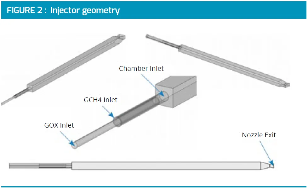
Figure 2 beside shows the injector geometry, consisting of two concentric pipes connected to a rectangular chamber. Via the inner tube Gaseous Oxygen (GOX) is injected, whereas Gaseous Methane (GCH4) is injected around it via the outer pipe. The purpose of the chamber is to create a recirculation zone, preventing the flame from blowing out. The recirculation of hot combustion products ensures a stable continuous combustion process after the engine is fired.
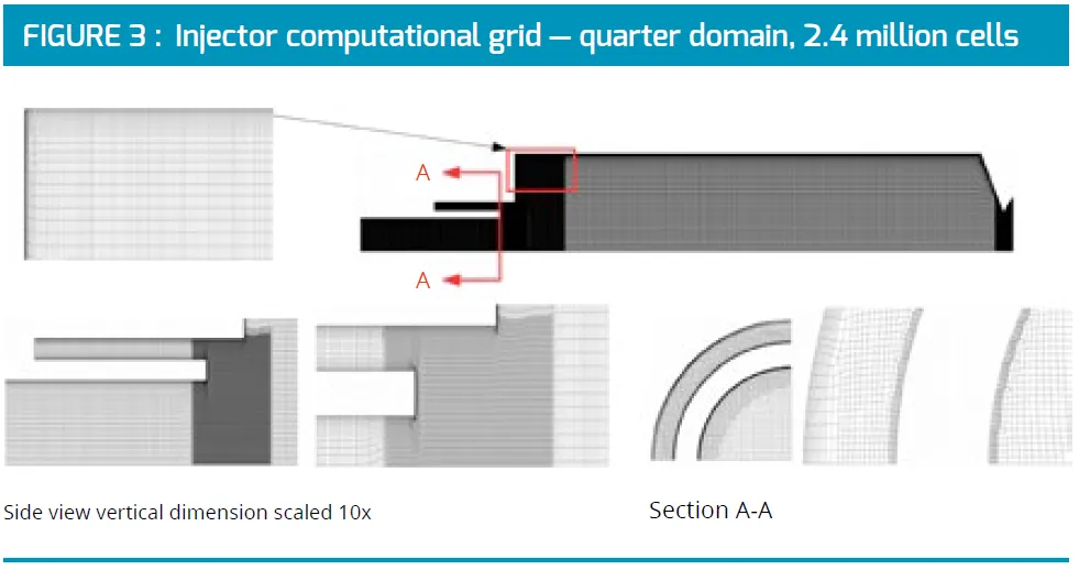
Two grids were generated: one coarse mesh at 1.8 million cells and one refined mesh containing 2.4 million cells with cylindrical viscous layers as shown in Figure 3.
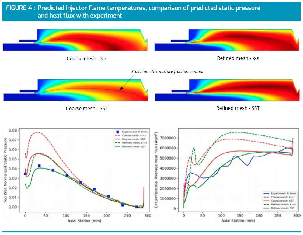
The simulation results were in good agreement with the measurement data. Figure 4 shows the simulated temperature field and a comparison between the simulated and experimental values of the static pressure and heat flux.
Optimisation of the cooling channel of the combustion chamber and nozzle of a rocket engine
To evaluate the potential of optimising the cooling channel, a generic test model was constructed with 180 cooling channels. In the baseline design, the cooling channel has an Aspect Ratio (AT) of 4.
Figure 5 displays their total pressure, heat flux and Thermal Barrier Coating (TBC) ,temperature predictions.
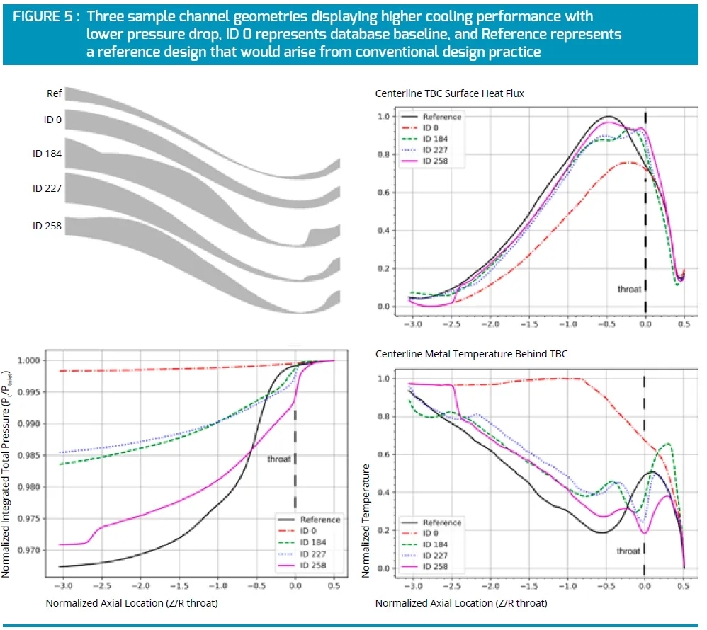
These three designs all included contractions of the CH4 channel in the vicinity of the nozzle throat and then an opening up of the passage down stream. On one hand this structure appeared to accelerate the channel flow in the throat region, resulting in higher heat flux, and therefore greater cooling in that area, and maintain attached flow downstream. On the other hand, the opening up of the channel downstream appeared to reduce total pressure losses compared to the reference design.
The uniform aspect ratio baseline (ID 0) produced the lowest total pressure loss by not accelerating the channel flow anywhere, but it subsequently demonstrated the lowest cooling performance. In the search for an optimised design, Self Organising Maps (SOM) were used to cluster the different samples in a space, such that highdimension space data can be visualised in 2D maps and identify the design that leads to the best compromise between cooling efficiency and pressure drop in the cooling channels.
By using SOMs the design IDs 184, 227, and 258 were singled out as the ones having the most promising characteristics.
Authors
Allan Grosvenor, Aerodynamics Lead, Masten Space Systems, USA
Jean-Charles Bonaccorsi, Technical Director, Cadence Design Systems
Jan Anker, Head of Combustion Modeling Group, Cadence Design Systems